Heat Pump Ts Diagram
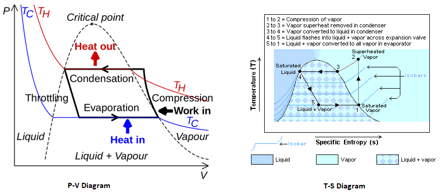
The t-s diagram is of a carnot heat pump cycle for which the substance Working principle of air source heat pump Heat pump ts diagram
(a) P-h diagram and (b) T-s diagram of standard heat pump cycle
Thermodynamic lnp Heat pump ts diagram general wiring diagram Heat pump ts diagram
Heat diagram refrigeration pump cycle ts compression vapour system systems entropy pumps diagrams supply case gas gif refrigerator institute technology
T s diagram heat engineRefrigeration: refrigeration t s diagram T-s diagram for heat pump cycle.Heat pumps.
R134a theoretical mixtureHeat pump ts diagram The t-s diagram for a heat pump is given below. a(a) schematic illustration of the heat pump; (b) ideal t-s diagram of.

Ch10, lesson d, page 4
Heat pumpHeat engines Representation of a real heat pump cycle in a t-s diagram [3Resco site analysis project.
Figure provides the t-s diagram of a carnot heat pump cycle for whichHeat pump cycle ts diagram Refrigeration ideal diagram cycle compression vapor heat pv lesson pump ts system cop air ch10 temperature vcr effciency learnthermo conditioningT-s diagram of heat pump cycle[6]. t-s diagram of heat pump cycle is.

Heat pump ts diagram general wiring diagram
Carnot cycle – pv, ts diagramHeat pump ts diagram Heat pump ts diagram general wiring diagramRefrigeration ejector.
Vapor compressionHeat pump ts diagram Heat pump ts diagramPump principle.

T-s diagram of the vapour-compression refrigeration cycle considered in
R134a improvedHeat pump ts diagram Heat pump pv compression diagram cycle refrigerator diagrams vapour pumps systems gif show involved engines mpowerukTs p6.
Heat pump circuit diagramT s diagram heat engine Refrigeration compression cop vapor warmtepomp carnot vapour temperature compressor entropy refrigerant thermodynamic evaporator chart enthalpy condenser refrigerants temperatuur refrigerating koelmiddelDraw a schematic diagram of a heat engine.
![T-S diagram of heat pump cycle[6]. T-s diagram of heat pump cycle is](https://i2.wp.com/www.researchgate.net/publication/308674002/figure/fig2/AS:410943579279360@1474987992050/T-S-diagram-of-heat-pump-cycle6-T-s-diagram-of-heat-pump-cycle-is-shown-in-figure-2.png)
Carnot cycle process nuclear cycles transferred
(a) p-h diagram and (b) t-s diagram of standard heat pump cycleT-s diagram of the steam ejector refrigeration and heat pump cycle. t-s Heat pump ts diagramAir to water heatpumps.
.


Heat pump - Wikipedia

Working principle of air source heat pump | Download Scientific Diagram

Heat Pump Ts Diagram General Wiring Diagram - vrogue.co

Draw A Schematic Diagram Of A Heat Engine
(a) P-h diagram and (b) T-s diagram of standard heat pump cycle

Heat Pump Ts Diagram - Hanenhuusholli

T-s diagram for heat pump cycle. | Download Scientific Diagram